2012 Cadillac CTSv Auxiliary fuel system install
Here is some pictures and information on my installation of my Aux fuel system on my 2012 Cadillac CTSv.


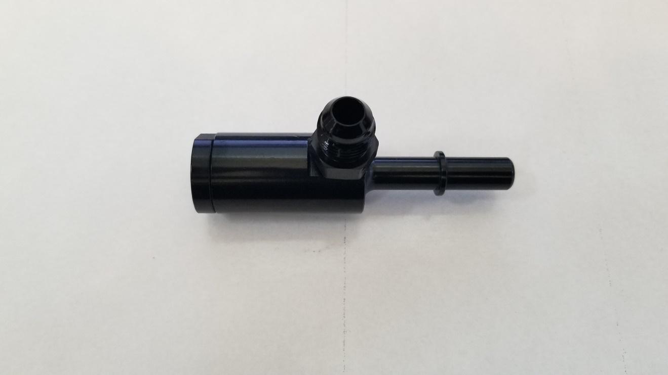
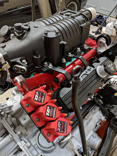
The photo above is of the Auxiliary fuel kit that I purchased for my 2012 Cadillac CTS v everything was included in this kit.

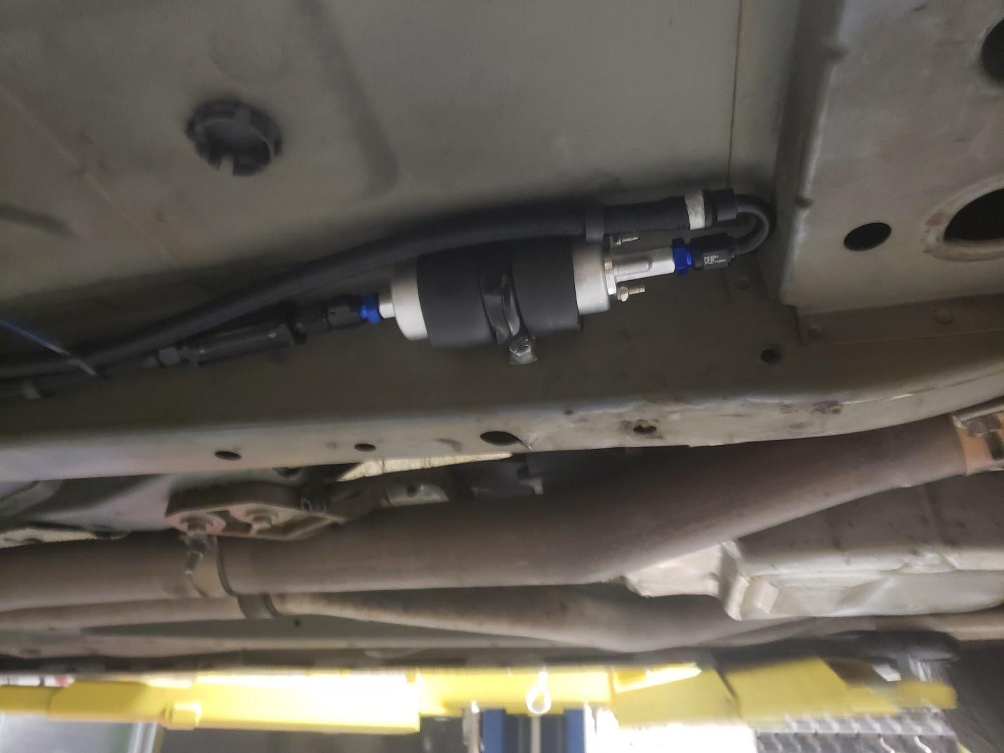
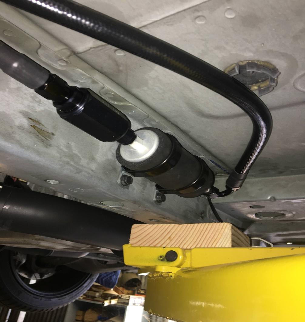
Above shows a photo of where I installed the Aux pump on my 2012 CTSv this is looking for the passenger side of the car just behind the front wheel looking towards the drivers side front wheel.

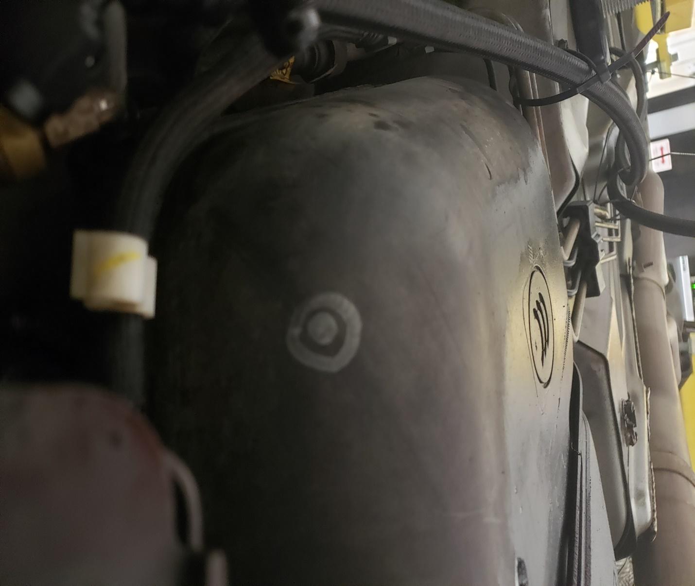
This photo above is looking from the passenger side at the fuel tank where the fitting is drilled and tapped into the factory fuel tank of the CTSv
Below are the directions I received from where I bought my Auxiliary fuel kit from for my 2012 Cadillac CTS v
SKID MARK GARAGE
Axillary Fuel Supply
*Disclaimer: Our Axillary Fuel kits are designed to fit most late model GM vehicles with minimum modifications. This kit has been designed and installed on a gen 2 CTS-V but may require some amount of customization from you the installer. The basics are covered below along with pics from the installation on our 2011 Demo CTS-V. Again, you may choose to mount a few things differently, and this kit has the flexibility to allow you to do just that.
Included with your kit
- Preassembled fuel pump assembly.
- Hoses and fittings
- Wire harness and zip ties to secure it out of the way. (Your kit will contain a fully assembled wire harness package.)
- New tube of thread sealant, no need to use entire tube, just enough to coat the NPT threads of the inline fuel, tank fitting and pressure switch only. You can discard the rest. (do not use on the AN fittings)
- Bags containing a length of vacuum line, vacuum tee, various fasteners, and clamps
Tools and/or additional parts needed (not included in this kit)
Tools
- Drill, drill bit and tap. Drill bit size 37/64 and 3/8” NPT tap, can usually be purchased as a kit online or your local hardware store. (not included in this kit)
- Misc. wrenches to tighten fittings once installed
- Socket wrench and various sockets.
- Jack and jackstands or automotive hoist, drain pan or bucket to catch spilled fuel.
- Tools to remove right front wheel and wheel liner
- Screw driver assortment
- Safety glasses to protect your eyes from debris and fuel when drilling and working under your car will also be a smart idea.
Pre-installation prep work
- Drive the car, you want the fuel tank as empty as possible as you will be drilling a small hole in the fuel tank to attach the new feed line to the aux fuel system. We drove our car till it was nearly on fumes and still had some spillage. When the car says its on “e” there is probably another Gallon or so in the tank.
- Working in a well-ventilated area, Jack up the rear of the car, or use a hoist, making sure the rear of the car is several inches higher than the front to make sure as little as possible fuel spills when tapping the rear of the tank.
- A drain pan or bucket should be handy to catch any spilled fuel. Fire extinguisher and appropriate safety equipment also advised.
- Disconnect negative battery terminal as we will be working with fuel and electrical systems.
Installation begins!
Work under the car
- With the car raised and safely secured, we will now begin the work under the car. We begin with locating and marking our fuel tank on the passenger side of the tank as shown below. You will see the location which we have outlined and put a bullseye on to help you find it. This location is approximate and as long as you are within the general area you should be fine. Use the picture as a good ball park of where you want to be.
- With the location found, clear off any dust or road debris with a shop rag and prepare to drill this location with the 37/64” drill bit mentioned on the 1st page.
- Wearing eye protection and using medium but steady pressure, begin drilling your hole at a slow to medium speed to ensure a clean cut into the plastic. The tank is only approximately 1/8 thick so be prepared. Catch any loose plastic shavings as they fall and discard.
- Any leftover fuel will now spill out, so be prepared to catch it.

- We’ll allow the tank to continue draining and move forward to other tasks while it drains.
- If your car has a dust shield, remove the 10mm bolts/nuts securing it.
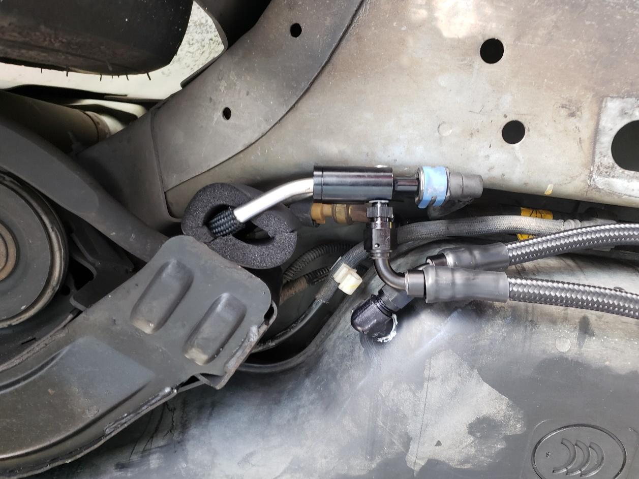
- With the dust tray removed and set aside, locate the fuel lines at the front of the tank just forward of where we drilled. One will have a blue clip. We will be working with the blue in this application. some knowledge of the car you are working on helps here. See the pics below for the end result.
- Remove the aux fuel pump hose assembly from the kit and find the fitting shown below. Remove it from the hose and prepare to install it inline.
- Carefully slide back (don’t fully remove) the blue clip from the fuel line feed and separate the 2 halves of the fuel line. Some left-over fuel may spill out of the fuel lines, a small rag should be sufficient to catch it.
- Quickly insert the fitting between the 2 halves and rotate the fitting so that the small threaded plug faces the drive shaft and the threaded AN fitting faces the passenger side of the car, reassemble the fuel lines and secure the blue clip. Some cars have tighter clearance and may need a little “adjustment” of the metal feed line further up the run to allow room for the adapter to be placed inline (removing a line bracket or adding a small bend to the feed up line is usually sufficient to add the additional room)
- Reattach the fuel line and the rest of the fuel pump assembly and route forward towards the passenger floor board. You can let it hang loose for now as we move onto the fitting at the tank. You will see the filter side of the aux pump assembly will face the rear of the car.
- Attached to the other hose on the pump assembly is a 90-degree fitting that has a 3/8” NPT on one end and the flare end is attached to the hose. Remove this fitting and locate the thread sealant tube that came in your kit.
- Open the sealant and liberally apply to only the NPT threads, working it into the threads with your finger but not so much that its dripping and set aside to allow it to set up. You have approximately one hour of working time before the sealant “cures” so be sure to mind the clock.
- Locate your 3/8” NPT tap mentioned on the 1st page and head back to the hole we drilled in the tank. By now it should be done draining so we can begin the tapping process.
- Insert the tap into the hole as square to the flat spot as possible and begin turning the tap into the hole. Ensure the tap is square to the hole and continue tapping until the tap as reached approximately ½ of the taps threads, then remove along with any debris.
- Once the threads are tapped and cleaned of any debris, wipe the area clean and dry, if you have any brake parts cleaner or denatured alcohol, that will work great and will not leave a residue, otherwise just use a dry rag and make sure it is clean.
- Grab the fitting we just applied the sealant to and insert the NPT thread into the freshly tapped hole. It may be hard to start at 1st but apply even pressure as you turn it in by hand will work, be sure to not cross thread it and keep it square to the hole. Here a ¾” or 19mm wrench can be used to provide leverage when threading the fitting into the hole.
- NPT threads are tapered, meaning they will get tighter as you rotate the fitting into the hole. You may see a little of the sealant starting to build up around the threads as you go, just leave it for now as the threads will continue to collect it as needed as they go in.
- At approximately ¾ of the threads, stop and position the fitting to face similar to this. (do not bottom out the fitting)

- We’ll now start rouging the included hoses. View photos in step 24 below of completed install to see where the best routing and which connection goes where. Once routed we’ll attach the pump to the frame and the hoses to each of their destinations.
- For now, we will leave the fittings finger tight to allow movement while will secure the pump assembly to the car.
- Back to the fuel pump assembly. Included in your kit is a single bolt and lock nut that will utilize an existing hole in the frame to located and mount the pump assembly. Additionally, you will find several rubber coated hose clamps and self-tapping screws to secure the lines from the pump to the tank and a larger one that will attach to the underside of the car and hold the pump securely in place. See the examples here for placement. (you will need to reach a wrench into the larger opening on the bottom of the frame to secure the nut from inside the frame-rail., Sometimes adding a small piece of tape to one side of a boxed ended wrench is perfect for holding a nut while attaching the bolt from the outside.) Note at this point you’ll also be attaching the short ground wire attached to the pump, to the mounting bolt
Your Kit may include the new Black bracket with 2 bolts to utilize 2 clamps for mounting your pump to the frame. If so, it’ll look like this when mounted:
- With the pump in place and mostly secured, we will now go back and snug the fuel fittings, using a wrench or 2, snug the fittings tight, but be mindful not to over torque them, these are aluminum fittings and too much force will ruin them. We will check for leaks once finished so we can go back and re-tighten any that need it later.
- See finished examples below for reference fitment on our 2011 Demo car:


Lastly, don’t forget to secure the fuel lines with the included clamps and zip ties. Our example above shows the hoses securely mounted and routed along the frame.
Onto the Wiring portion
- If using a lift, lower the car back down to allow you to work under the hood.
- In your kit, located the Hobbs pressure switch that looks like this. It was prewired and designed to be mounted in relative proximity to the relay where you’ll have easy access later should you want to adjust the pressure sensitivity (pressure adjust covered on last page). The treaded side of the Hobbs will have a brass barbed fitting for your vacuum line attachment.
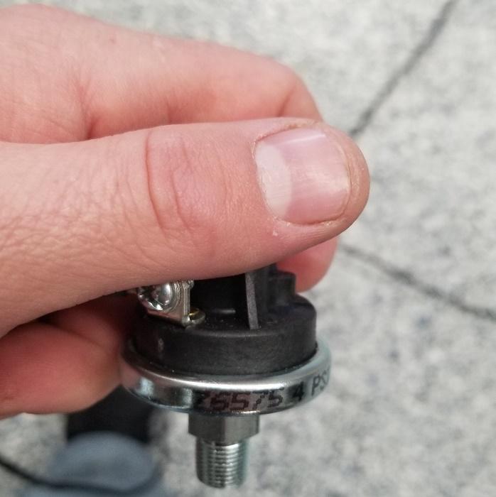
- This switch is pre-wired and ready for you to simply add the vacuum line to your manifold. The threaded end can also be attached directly to a “manifold” as well, but the preferred method is a vacuum line to limit wire length. (Wires going to the switch would need to be extended if you opt for this route).
- If your car has an aftermarket boost adder, you should have some sort of vacuum manifold or “tree” to feed a mechanical boost gauge, bypass valve etc.. similar to this.
- Take the length of vacuum line from the kit and trim about a 2” section off the end. Using the included tee, tap your manifold here for boost reference.

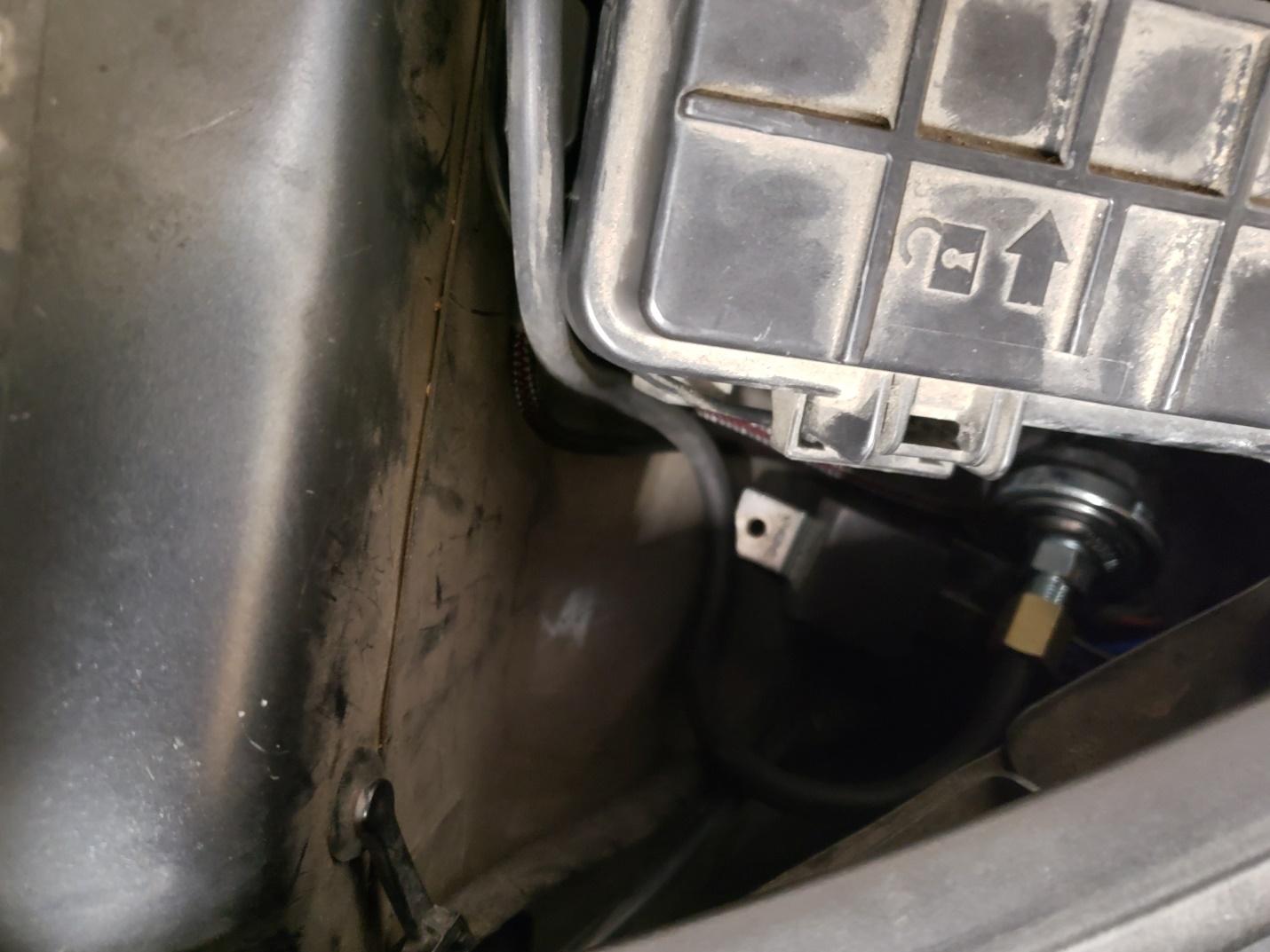
- Safely route the Vacuum line back to the hobs switch avoiding any pinch points or hot parts that would melt the hose (exhaust manifolds, turbos etc) You will ultimately place the relay harness and switch assembly next to the fuse box and secure it to a bolt and or a zip-tie on the inner fender. Use included zip to secure any loose wires and vacuum lines for best appearance and safety. Then tuck down next to the fuse box as shown below. (if you chose to bolt it to the fender, that’s also an option)
- Taking the other side of the harness, (long single power lead to pump) and route into the fender towards the back of the car. Removing the front wheel and dropping the fender liner at this time will aid in routing the wire to its ultimate goal, the new fuel pump.
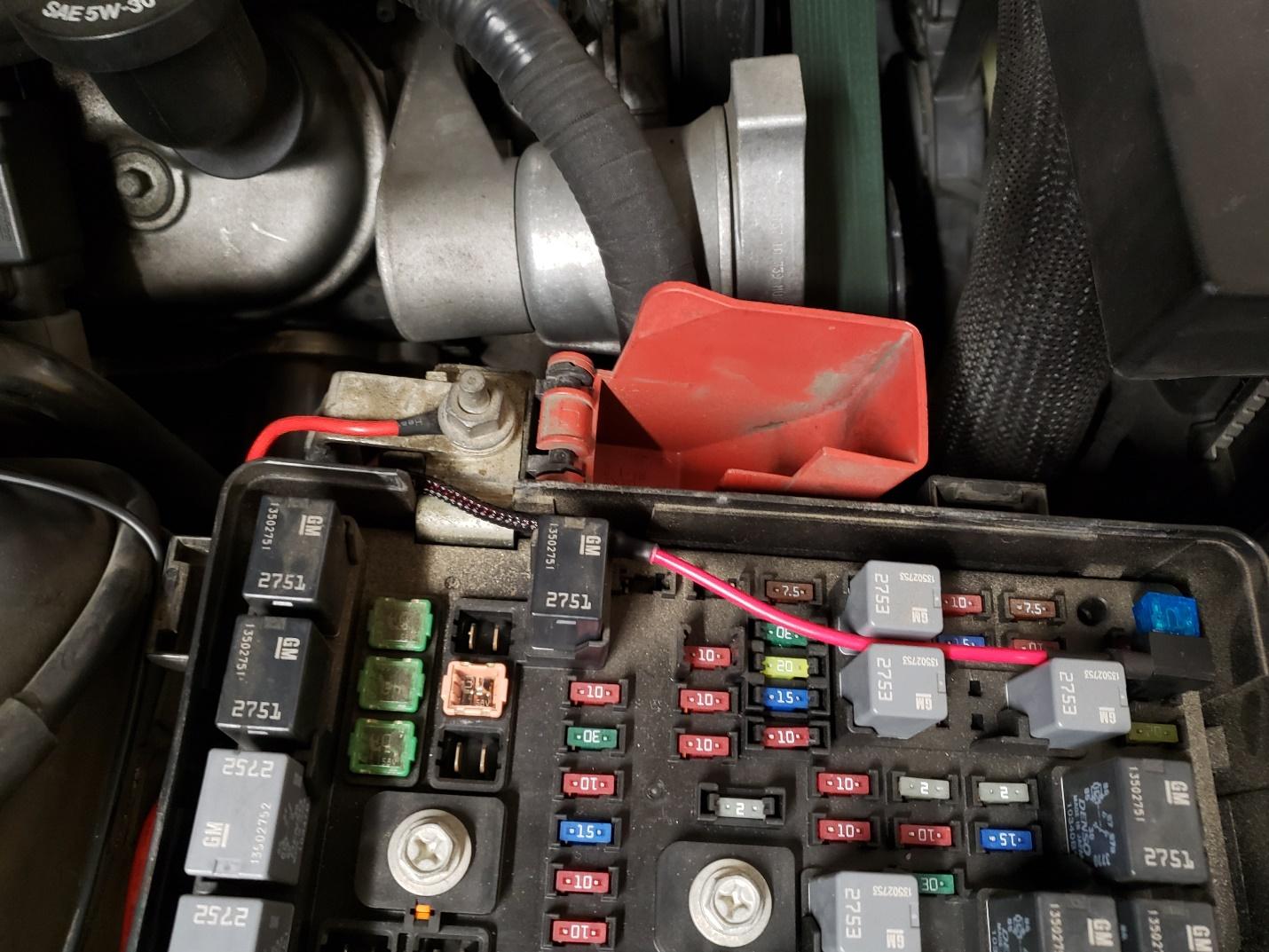
- Located the power supply under this cover at the fuse box. Attach the ring terminal marked “constant” there, and route the lead marked “switched” as shown to fuse location 70 (remove existing fuse and insert our dual fused jumper harness in its place) route wire as shown out of the fuse box.
- For the lead marked “ground” attach it to the ground strap next to the fuse box or the smaller stud on the fender well
- Secure any under hood wires with zip ties to your liking and close the hood, for now we are done under hood.
- Raise the car back up and finish routing the power lead from the fender well to the pump, making sure to route it from and moving parts or sharp edges, connect the red tipped lead with e “pump 12v” tag to the pump + terminal, (the negative terminal should already be attached to a short ground wire and to the frame where the pump mounts) We chose to route our lead through the inner fender well. You can do the same, simple remove the front tire for best access, lower the fender liners by removing the clips and route you wire safely behind the fender liner.
- Secure the wire with included zip ties and tuck away any slack. Re assemble the fender liner and re-attach the passenger front wheel.
- We will now double check the fuel fittings for snug, zip tie any hose that hangs low to the under-body holes. Lower the car, add additional fuel if your tank was empty, it’s time to start it up and check for leaks. Reattach the battery if disconnected.
- With the car started and warm, look underneath, touch the fuel fittings and make sure no wet fuel is present on any fittings, if found, shut off car, snug a bit tighter, and verify leak is gone. Repeat steps until no leaks are found.
- Reattach the dust cover if you removed one, at this point you can snug up the pump mount as well. Installation is complete.
Adjusting the trigger point of the Hobbs switch.
- Your Hobbs switch is preset at ~4psi boost pressure which is suitable for most applications. You may custom tailor it to come on sooner or later depending on your need.
- If you find you need to adjust the pressure setting on the Hobbs Switch, there is a small rubber cover on the top of the plastic stem of the housing, underneath it a hex head set screw, turn it clock wise (in) and the pressure required to trigger it goes up, counter clockwise (out) and the pressure required goes down. The switch included has a window of ~1psi-~10psi. Higher rated switches are available on a custom order basis. Test and tune as you would with any adjustable fuel modification to find what works best for you.
- If you monitor fuel pressure on a gauge or via your preferred tuning software, you should now see the increased low side fuel pressure under load. Some cars may need the FPCM programmed to take full advantage of the increased fuel, consult your tuner for more info
That’s it! Your install is complete and you are ready to go tear up the competition.
Our goal is to offer high quality, in demand products for your car for less than the competition. To help keep our prices low, we keep our overhead low. Paid advertising is kept to a minimum, and forum sponsorships are non-existent.
That means we need your help spreading the word. If you could take a few moments and drop us a review on a board or 2 and rate us or tag us on Facebook, that would be greatly appreciated.
Our Auxiliary fuel systems are manufactured in house and use proven top-quality components and tested before they ship. Should you have a problem with your kit due to failure of a component within the 1st year, we will replace it at no charge. Physical damage, nor faulty installation of the kits are covered under this policy.
Thank you for your business.
- Jeremy Dominick
Owner- Skid Mark Garage

Comments
Post a Comment